Exploring IC Package Miniaturization: QFP and QFN
A deeper look at quad flat packages and quad flat no lead packages
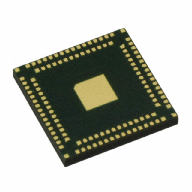
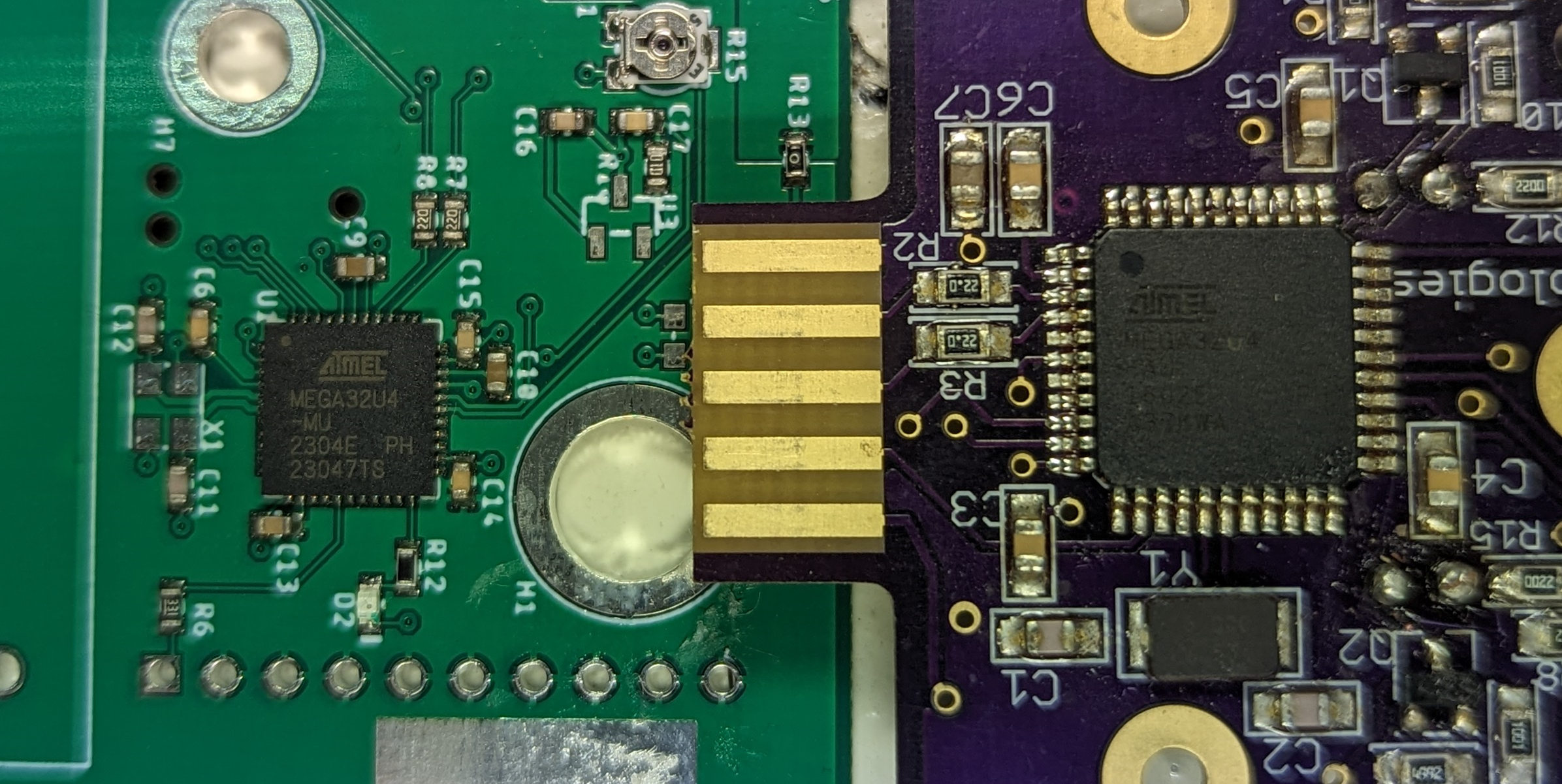 An ATMega32U4 44pin QFN (Left) and QFP (right) package.
This is the second blog post in our series about the miniaturization of IC packages. To see an overview of the four types of packages we will look at in this series, visit the first post here. In our third post we exmine the move to BGA and in our fourth post we have an indepth look at WLCSP. In our fifth post we share all the data we collected in this blog series.
Package Data
We compiled 44 different unique QFP packages and 35 different unique QFN packages for this analysis. These packages came from queries of Digi-Key’s list of in-stock microcontrollers. There are more packages out there, but some are for obsolete or out-of-stock components, and we wanted the dataset to represent the packages in use today.

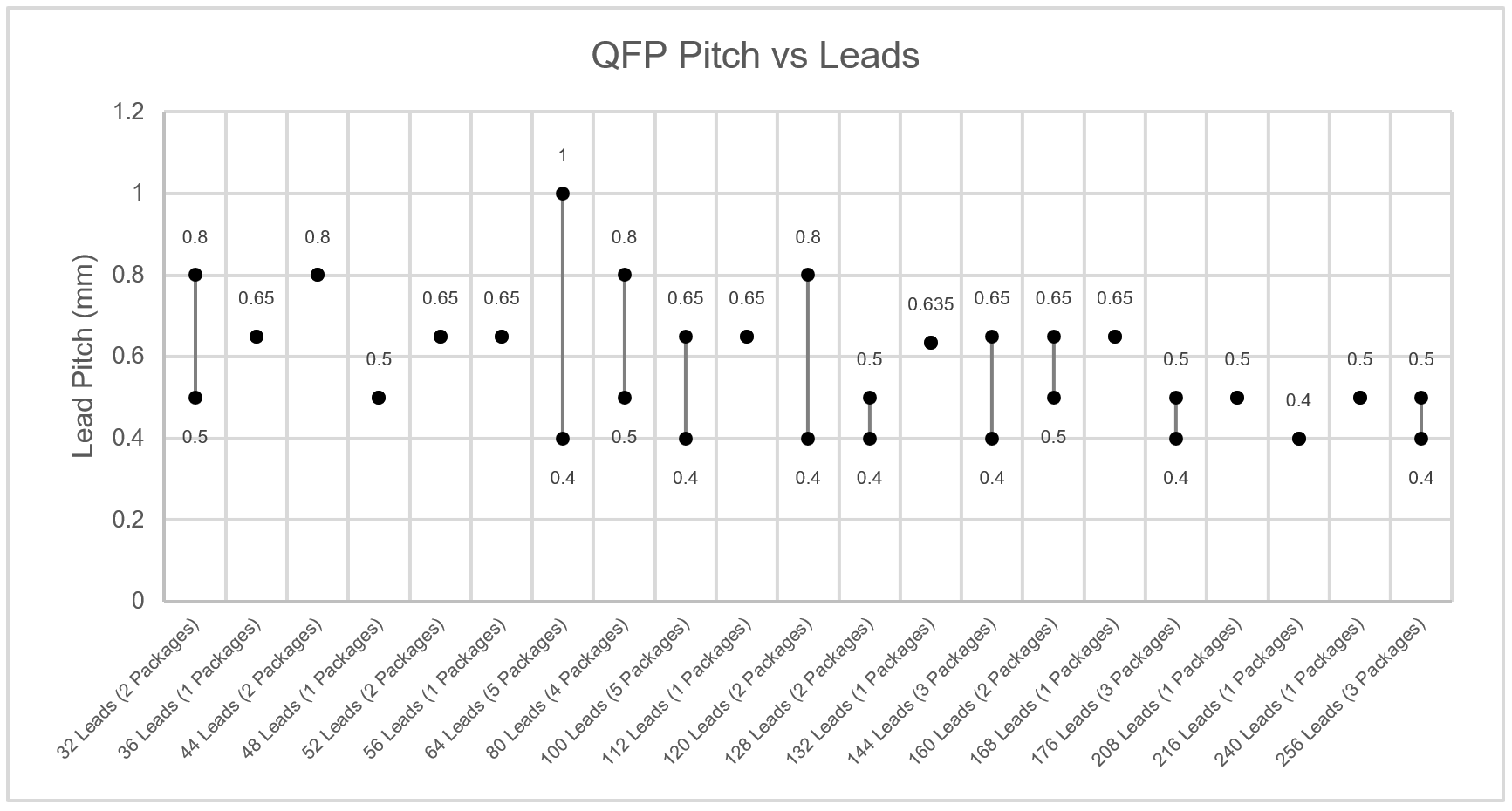
Quad Flat Packages
The pitch varies from 1mm to 0.4mm, with higher lead count packages generally having smaller pitches.
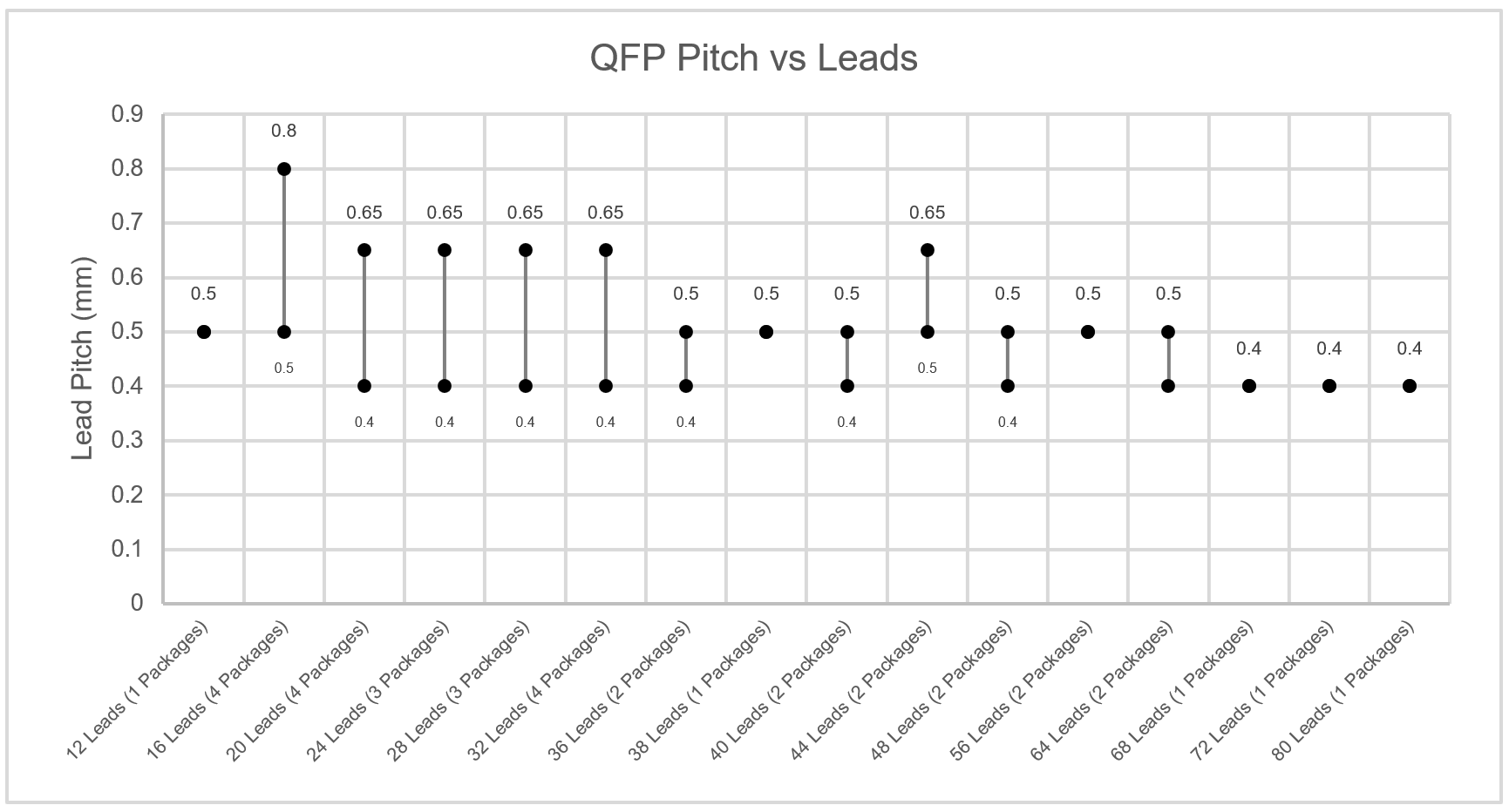
Quad Flat No Lead
The pitch varies from 0.8mm to 0.4mm, with all chips generally having a 0.4mm pitch option, but only smaller chips having larger pitches.
Limits on Density
The quad flat packages are limited in the number of leads for each package by the minimum possible pitch, which is 0.4mm, and the density of contact is limited by the ratio of the perimeter to the area of the package. The number of leads for the IC is proportional to the length of the sides of the IC, while its area grows by the square of the length of the sides of the IC. This is why the highest lead count is 256 for QFPs and 80 for QFNs. QFP packages are also further limited by the need for the “gull-wing leads” on each side. These are typically 1mm long, resulting in the area required for the package being 2mm larger on each side than the package itself. This limits the effective lead density for low lead count QFP chips when compared to packages like Small Outline Integrated Circuit with leads on only 2 sides.
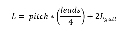
Max Theoretical Lead Density
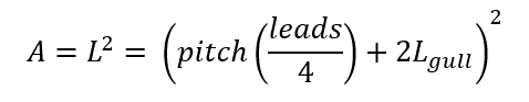
The max theoretical lead density was derived from the minimum pitch, 0.4mm, and the typical gull-wing length, 0mm for QFNs and 1mm for QFPs. The minimum side length of the IC is:
The area of the IC is then:
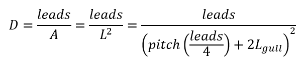
And the lead density is then:
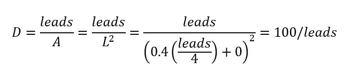
Which for QFNs is:
And for QFPs is:
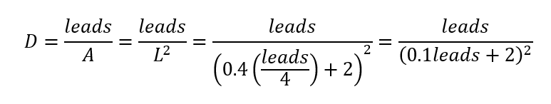
This shows the interesting phenomenon where for QFP packages below 20 leads, the lead density decreases.
Ways Around the Density Limits
There are some rare packages in each of these families designed to get around the lead limits. Because of the rarity, neither one was included in this dataset. For QFNs, we saw double-row QFN, where a second set of leads exists inside the outer set. This is bordering on becoming a Land Grid Array or BGA type of package.
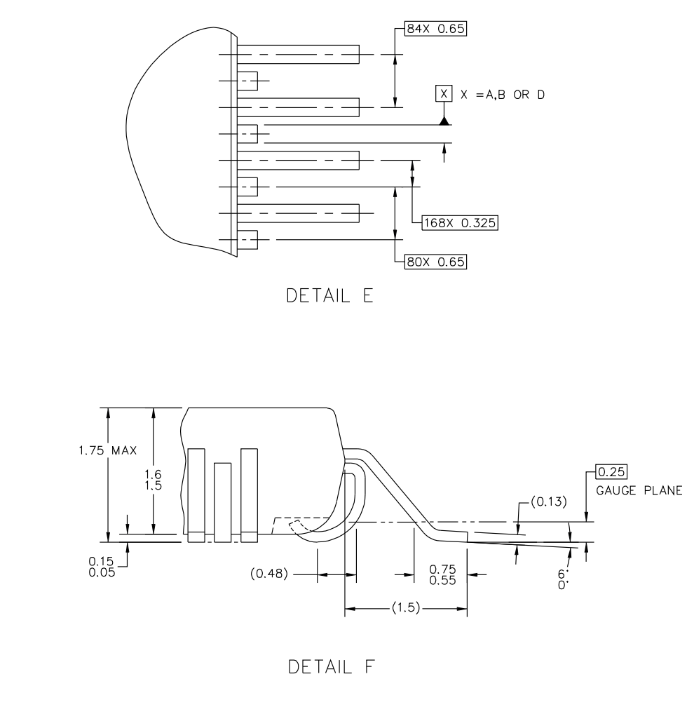
For QFP packages, we saw High-Density QFN packages with 0.325mm pitch and every other lead folded down under the chip, giving the footprint the required space between pads and an effecitve pitch of 0.65mm.
Get More Information
Part 1: Miniaturization of IC Packages
Part 3: The move from QFN and QFP to Ball Grid Array
Part 4: The Rise of Wafer Level Chip Scale Packages (WLCSP)
Part 5: All the IC Package Data in One Place: QFP, QFN, BGA, and WLCSP
For more information sign up at here.