Defining Circles & Polygons
Best practice on creating circles & polygons in EAGLE
Why are we writing this?
When designing a printed circuit board through EAGLE or other CAD softwares it is essential to understand how subtle design choices will influence manufacturability. When a PCB is designed in CAD it must be converted to the industry standard file format known as a Gerber file for the manufacturing process. This blog post will provide a basic introduction to some best practices for defining circles and polygons such that they match design intent when translated to gerber format and are manufactured with confidence!
What is a gerber? Why should you care?
Firstly, what exactly is a Gerber file? A gerber file is the industry standard file format used to manufacture the PCB boards according to the CAD design. The gerber format can be thought of as a series of vectors which represent the features on different board layers. Put simply, a gerber file uses a series of “flashes” and “drawings” which are created using “apertures'' and the respective vector coordinates to represent the features of a PCB.
Gerber Format Explained
To better understand the concepts behind the gerber file format consider the following analogy of a gerber as a hand-drawn picture. An “aperture” can be thought of as the tip of a pen used to draw the image, and a gerber file contains different sized apertures to draw different sized features, much like an artist with different drawing utensils. A “drawing” therefore can be thought of as a line, arc, or other shape which is created by moving the pen, or “aperture”, across the page. A “flash” however is different from a “drawing”, and can be thought of as a printed image or stamp of a unique shape such as a square, circle, or other simple shape which is then applied to the paper instead of drawn with a pen.
How does Gerber Translation affect PCB design?
Now that the gerber file is better understood, what does this have to do with accurately and precisely defining circles and polygons? A staple of PCB design is the humble circle and it is commonly used for creating board features such as copper pads, vias, through holes, pin indicators, and so much more. While it may seem straightforward to define a circle (or any other polygon for that matter) of a specific size to match the intended design there are some features that must be considered.
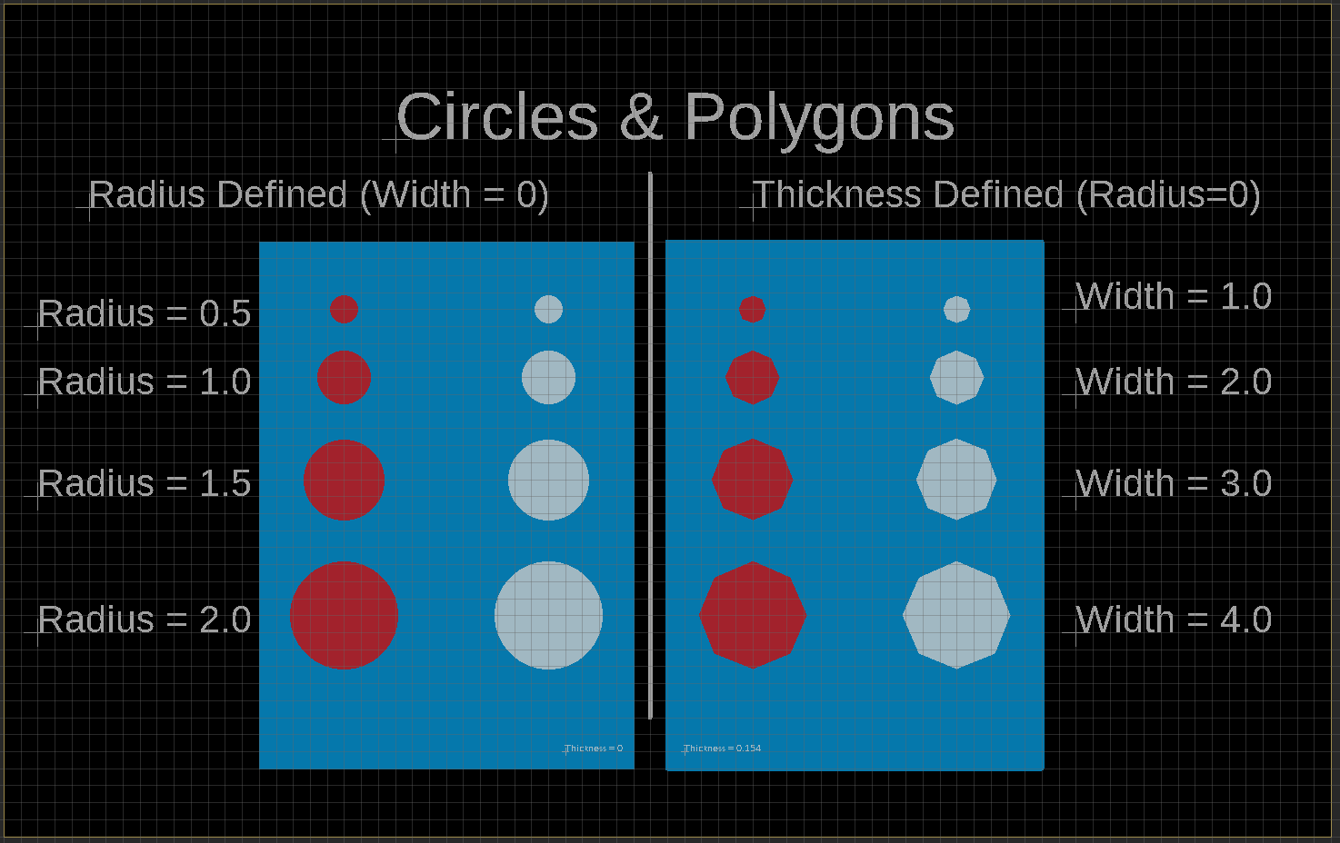
When defining a circle in EAGLE the user must define “width” and “radius”. In order to create a precise circle, the user must set width=0, and then alter the radius value to create a perfect circle “flash” image. Doing the opposite process by defining a circle by width, with radius=0 will cause the circle to be shown as imperfectly round. This occurs because instead of creating a “flash” image, the gerber translation process will instead create a polygon. The “Circles & Polygons” board design shown in the image below demonstrates this effect. Notice in the image below how the circles on the right side of the design are represented as octagons instead of a true circle, and as a result will become represented as polygons in the gerber, rather than “flashes” which would be preferable.
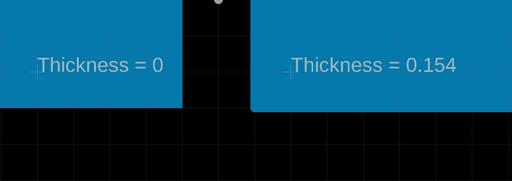
This effect can also have significant influence when attempting to create a copper plane of very precise dimensions. In the image below, the bottom edge of the copper planes from the above image are magnified to demonstrate the additional size added to the rectangle’s edge by not defining thickness=0.
In some instances these slight dimensional inconsistencies that occur during gerber translation go undetected. But there is a very real possibility that unintended design effects such as these are the difference between an accurately translated gerber resulting in a well manufactured PCB that precisely follows the original intended design, and a PCB which has electrical shorts, unintended overlaps or collisions, and design tolerances that are much tighter than necessary.